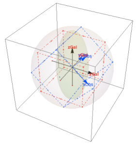
Figure 1
The appearance of images projected onto the observer plane depends on three angles by which observer coordinates are rotated about the simulation region. The first rotation by ϕOrient spins the projection onto the observer plane about the origin of the observer plane, the second rotation by θObs in determines the angle of the observer direction relative to the polar axis, and the third rotation by ϕObs corresponds to an observer flying around the polar axis in the azimuthal direction.
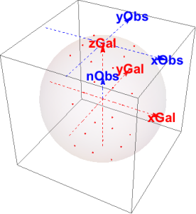
Figure 2
Images are sums of slices normal to the observer direction nObs projected onto the xObs-yObs plane. To change observer azimuth, the observer coordinates (blue) “fly” around the fixed simulation coordinates (red).